Bosch Serie 2 dishwashers offer reliable performance and innovative features, detailed in the manual. They balance efficiency with user-friendly operation for everyday cleaning needs.
Overview of the Serie 2 Range
The Bosch Serie 2 range presents a diverse selection of dishwashers, comprehensively covered within the manual. These models prioritize practicality and efficiency, catering to various kitchen sizes and household demands. Expect features like EcoSilence Drive for quiet operation and AquaStop for leak protection. The manual details variations in capacity, program options, and specific model functionalities, ensuring users can maximize their appliance’s potential. It’s a solid choice for reliable, everyday dishwashing.
Key Features and Benefits
Bosch Serie 2 dishwashers, as outlined in the manual, boast several key advantages. The EcoSilence Drive ensures exceptionally quiet operation, while AquaStop provides reliable leak protection. Features like VarioFlex baskets maximize loading flexibility. The manual details how to utilize programs like Eco and Intensive for optimal cleaning. Benefits include energy efficiency, convenience, and long-term reliability, making them a practical choice for modern kitchens.
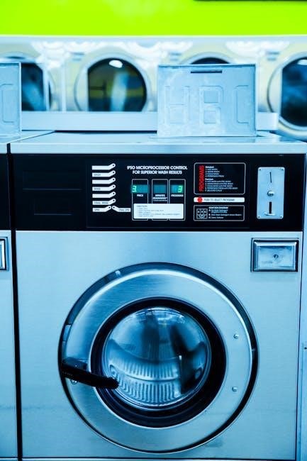
Understanding Your Dishwasher’s Control Panel
The Bosch Serie 2 dishwasher manual details the control panel’s functions, including program selection, start/pause, and special options for customized cleaning cycles.
Buttons and Symbols Explained
Refer to your Bosch Serie 2 dishwasher manual for a comprehensive guide to each button and symbol. Common icons include program selection (Eco, Normal, Intensive), start/pause, and special functions like VarioSpeed or Extra Dry. Understanding these controls allows for optimal program choices and customized wash cycles, ensuring efficient and effective cleaning performance tailored to your dishwashing needs.
Display Indicators and Error Codes
The Bosch Serie 2 dishwasher manual details all display indicators, such as program progress, remaining time, and selected options. Error codes signal issues – consult the manual for specific meanings (e.g., water supply, drain blockage). Addressing these promptly prevents damage and ensures optimal performance. Ignoring codes may lead to recurring problems or void the warranty.

Loading Your Dishwasher Correctly
The Bosch Serie 2 dishwasher manual emphasizes proper loading for optimal cleaning. Avoid overcrowding, ensuring water reaches all surfaces for efficient results.
Upper and Lower Rack Placement
According to the Bosch Serie 2 dishwasher manual, the upper rack is ideal for glasses, cups, and smaller items, positioned facing the spray arm. The lower rack accommodates larger, heavily soiled pots, pans, and plates. Ensure items don’t obstruct the spray arms’ rotation. Adjustable rack heights offer flexibility for varied dish sizes, maximizing space and cleaning performance. Proper placement prevents re-washing and ensures sparkling results.
Cutlery Basket Usage
The Bosch Serie 2 dishwasher manual details cutlery basket loading; alternate utensil direction to prevent nesting and ensure thorough cleaning. Separate knives, forks, and spoons for optimal water circulation. Some models feature a dedicated cutlery drawer with individual slots. Avoid overloading, allowing water to reach all surfaces. Secure long utensils horizontally to prevent them from blocking the spray arms.

Detergent and Rinse Aid
The Bosch Serie 2 dishwasher manual recommends using dishwasher detergent and rinse aid for optimal results. Proper dosage, as indicated, ensures sparkling clean dishes and prevents spotting.
Recommended Detergent Types
The Bosch Serie 2 dishwasher manual details acceptable detergent types. Powder, gel, and tablet detergents are generally suitable, but avoid those containing preliminary rinsing agents. Using high-quality detergents specifically formulated for dishwashers is crucial for effective cleaning and preventing residue. The manual advises against using hand dish soap, as it creates excessive suds, potentially damaging the appliance and reducing cleaning performance. Always follow the detergent manufacturer’s instructions for proper dosage.
Proper Dosage and Compartment Filling
The Bosch Serie 2 dishwasher manual emphasizes correct detergent dosage. Overfilling can cause residue, while underfilling leads to poor cleaning. Fill the main wash compartment before each cycle, respecting the maximum fill line. For rinse aid, fill the designated compartment to optimize drying. The manual illustrates compartment locations and provides dosage charts based on water hardness and load size, ensuring optimal results.
Wash Programs Explained
The Bosch Serie 2 dishwasher manual details various programs – Eco, Intensive, Normal, and Quick – each optimized for specific dish soil levels and cleaning needs.
Eco Program – Energy Saving
As outlined in the Bosch Serie 2 dishwasher manual, the Eco Program is designed for lightly soiled dishes, prioritizing energy and water conservation. It utilizes lower temperatures and extended wash cycles to achieve optimal cleaning results while minimizing environmental impact. This program is ideal for daily use and contributes to reduced utility bills, offering a sustainable cleaning solution for your household.
Intensive Program – For Heavily Soiled Dishes
The Bosch Serie 2 dishwasher manual details the Intensive Program, specifically for tackling heavily soiled cookware, pots, and pans. This program employs higher water temperatures, increased spray pressure, and a longer wash duration to effectively remove stubborn food residues. It’s recommended for items with baked-on grime, ensuring a thorough and hygienic clean, despite increased energy consumption.
Normal Program – Everyday Use
As outlined in the Bosch Serie 2 dishwasher manual, the Normal Program is designed for daily dishwashing needs. It offers a balanced approach to cleaning, effectively removing typical food soils while optimizing water and energy usage. This program is suitable for a mixed load of dishes, providing reliable results for everyday use without excessive cycle times.
Quick/Express Program – For Lightly Soiled Dishes
The Bosch Serie 2 dishwasher manual details the Quick/Express Program as ideal for dishes with minimal food residue. This shortened cycle delivers a fast and efficient clean, perfect when time is limited. It’s recommended for lightly soiled items like glasses or recently used plates, offering convenience without compromising cleaning performance.

Maintenance and Cleaning
The Bosch Serie 2 dishwasher manual stresses regular cleaning of spray arms and filters for optimal performance. Consistent upkeep ensures longevity and efficient dishwashing.
Cleaning the Spray Arms
According to the Bosch Serie 2 dishwasher manual, regularly inspect and clean the spray arms to prevent clogging. Remove the arms – typically by unscrewing or unclipping – and use a toothpick or fine wire to clear any food particles from the nozzles. Ensure free rotation after cleaning; blocked nozzles reduce cleaning effectiveness. Rinse thoroughly before reattaching, guaranteeing optimal water distribution during cycles and maintaining peak dishwasher performance.
Filter Cleaning Procedures
The Bosch Serie 2 dishwasher manual details a crucial step: filter cleaning. Regularly remove the cylindrical filter system – usually located at the base of the dishwasher. Rinse under running water, removing food debris with a brush. A coarse filter catches larger particles, while a fine filter traps smaller ones. Reassemble correctly, ensuring proper sealing to prevent particles from recirculating and impacting cleaning performance.
Dishwasher Interior Cleaning
The Bosch Serie 2 dishwasher manual recommends periodic interior cleaning. Run an empty cycle with dishwasher cleaner, or use a vinegar solution in the upper rack. Wipe down door seals and the interior walls with a damp cloth. Avoid abrasive cleaners which can damage surfaces. This removes grease, limescale, and odors, maintaining optimal hygiene and performance.

Troubleshooting Common Issues
The Bosch Serie 2 dishwasher manual details solutions for typical problems like error codes, poor cleaning, or leaks, guiding users through quick fixes.
Dishwasher Not Starting
According to the Bosch Serie 2 dishwasher manual, if the unit fails to start, first check the power supply and circuit breaker. Ensure the door is firmly latched, as a safety mechanism prevents operation if not properly closed.
Verify the Start button was pressed and no error codes are displayed. Consult the manual’s troubleshooting section for specific error code meanings and recommended actions, potentially involving a reset or service call.
Poor Cleaning Performance
The Bosch Serie 2 dishwasher manual suggests several checks for inadequate cleaning. Confirm proper loading – avoid overcrowding and ensure spray arms rotate freely. Verify sufficient detergent is used, appropriate for water hardness levels (adjustable in settings). Clean the filter regularly, as blockages reduce cleaning efficacy. Select the correct wash program for the soil level of the dishes.
Water Leaks
The Bosch Serie 2 dishwasher manual advises inspecting door seals for damage or debris. Check the water inlet and drain hoses for cracks or loose connections. Ensure the dishwasher is level to prevent water spillage. If leaks persist, the manual recommends contacting a qualified technician for assistance, as internal component issues may require professional repair.

Safety Precautions
The Bosch Serie 2 dishwasher manual stresses electrical safety and proper grounding. Always supervise children and utilize the child lock function when activated.
Electrical Safety Guidelines
The Bosch Serie 2 dishwasher manual emphatically advises against modifying the power cord or using extension cords. Installation must adhere to local electrical codes, performed by a qualified technician. Never attempt self-repair of electrical components; disconnect power before cleaning or maintenance. Grounding is crucial to prevent shock hazards, and the appliance should never be used with a damaged cord or plug. Always ensure the voltage matches the dishwasher’s specifications.
Child Lock Function
The Bosch Serie 2 dishwasher manual details activating the child lock to prevent accidental operation. Typically, holding specific buttons simultaneously (often Start and a program button) enables this feature, illuminating an indicator light. This secures the control panel, protecting children from altering settings or starting cycles. Refer to your specific model’s manual for precise instructions on activation and deactivation.

Technical Specifications
The Bosch Serie 2 dishwasher manual lists dimensions, capacity, water consumption, and energy efficiency ratings. These details aid in installation and usage planning.
Dimensions and Capacity
The Bosch Serie 2 dishwasher manual provides precise dimensions – height, width, and depth – crucial for fitting the appliance into your kitchen space. It details internal capacity, typically expressed in place settings, indicating how many dishes it can accommodate. Variations exist within the Serie 2 range; therefore, consulting your specific model’s manual is essential for accurate measurements and capacity information. Understanding these specifications ensures proper installation and optimal usage.
Water Consumption and Energy Efficiency
The Bosch Serie 2 dishwasher manual outlines water usage per cycle, a key indicator of resource efficiency. It details energy consumption, often displayed using energy efficiency class ratings, helping you understand operating costs. The manual explains how to optimize cycles for lower consumption. Specific values vary by model; therefore, referencing your model’s manual is vital for accurate data and maximizing eco-friendly operation.
Error Codes and Their Meanings
The Bosch Serie 2 dishwasher manual provides a comprehensive list of error codes, explaining potential issues and troubleshooting steps for quick resolution.
Decoding Common Error Messages
The Bosch Serie 2 dishwasher manual details frequent error codes like E15 (water intake issue) or F02 (drainage problem). Understanding these messages, found within the manual, allows for self-diagnosis. Codes indicate specific malfunctions, guiding users toward solutions—checking water supply, clearing drains, or resetting the appliance. Referencing the manual’s troubleshooting section is crucial before contacting support, saving time and potential service costs.
What to Do When an Error Occurs
The Bosch Serie 2 dishwasher manual advises users to first pause the cycle when an error appears. Consult the manual’s error code section for a specific diagnosis and suggested remedy. Simple fixes, like resetting the appliance or checking the water supply, are often detailed. If the issue persists, note the error code before contacting Bosch support for further assistance, ensuring a quicker resolution.
Water Hardness Settings
The Bosch Serie 2 dishwasher manual details adjusting hardness levels for optimal cleaning; Proper settings, based on your water supply, prevent scaling and ensure sparkling dishes.
Adjusting Water Hardness Levels
Refer to your Bosch Serie 2 dishwasher manual to determine your local water hardness. Use the provided test strip or consult your water utility company. Access the dishwasher’s control panel and navigate to the settings menu. Select “Water Hardness” and input the corresponding level – typically ranging from 1 (softest) to 7 (hardest). Incorrect settings can lead to spotting or reduced cleaning performance, so accuracy is crucial for optimal results and longevity of the appliance;
Impact of Water Hardness on Performance
The Bosch Serie 2 dishwasher manual explains how water hardness affects cleaning. Hard water contains minerals that can leave spots and film on dishes. It also reduces detergent effectiveness, requiring higher doses. Conversely, soft water may cause etching on glassware. Properly adjusting the water hardness setting ensures optimal cleaning, prevents damage, and maximizes the lifespan of your dishwasher, as detailed within the user guide.
Self-Diagnosis and Testing
The Bosch Serie 2 dishwasher manual guides users through test cycles to check functionality. It details how to identify potential internal leaks and confirm proper operation.
Running a Test Wash Cycle
According to the Bosch Serie 2 dishwasher manual, initiating a test wash confirms all components are functioning correctly. This diagnostic cycle, often accessed through a specific button combination, simulates a normal wash without detergent. Observe spray arm rotation, water intake, and drainage. The manual details expected cycle times and any displayed error codes during the test, helping pinpoint potential issues before regular use. Successful completion indicates basic operational integrity.
Checking for Internal Leaks
The Bosch Serie 2 dishwasher manual advises inspecting the floor around the unit after each wash for moisture. Carefully examine seals around the door, spray arms, and water inlet hose, as detailed in the manual; Run a cycle and visually check inside the dishwasher’s base for standing water. Addressing leaks promptly prevents damage and ensures optimal performance, following the manual’s troubleshooting guidance.
Warranty Information
The Bosch Serie 2 dishwasher manual details warranty coverage, typically one year for parts and labor. Registration is crucial for claim eligibility, as outlined within.
Coverage Details
Bosch Serie 2 dishwasher manual specifics reveal the limited warranty covers defects in materials and workmanship. Parts are generally covered for one year from the purchase date, while labor has the same duration. This doesn’t include damage from misuse, improper installation, or normal wear. Extended warranties are available for purchase, offering broader protection and longer coverage periods, detailed in supplemental documentation.
How to Claim Warranty Service
To initiate a warranty claim for your Bosch Serie 2 dishwasher, consult the manual for authorized service centers. Contact Bosch customer support with your model and serial number, purchase date, and a description of the issue. Proof of purchase is essential. They’ll guide you through the process, potentially scheduling a technician visit.

Contacting Bosch Support
The Bosch Serie 2 dishwasher manual lists customer service phone numbers and online resources. Access FAQs and support via the Bosch website for assistance.
Customer Service Phone Numbers
For immediate assistance with your Bosch Serie 2 dishwasher, referencing the manual can direct you to specific support lines. While direct numbers vary by region, the Bosch customer service website provides localized contact information. Generally, a toll-free number is available for appliance inquiries. Expect potential wait times during peak hours. Online chat support, often linked from the manual’s digital version, offers a convenient alternative. Always have your model number ready for quicker service.
Online Resources and FAQs
The official Bosch website hosts a comprehensive library of resources, including a digital version of the Serie 2 dishwasher manual. Extensive FAQs address common issues, troubleshooting steps, and usage guidance. Video tutorials demonstrate loading techniques and maintenance procedures. Bosch’s online community forums allow users to share experiences and solutions. Registration unlocks personalized support and access to exclusive content related to your appliance model.